Adam's Workspace
Happy coding
Categories
- latex
- Numerical Receipes
- Other
- Linux
- C++
- ROS
- Android
- MySQL
- OMNet++
- Software-and-Tools
- emacs
- Assembly
- BuzzBuzz
Meta
Search
Tag Cloud
New Comments
New Messages
Archive
RSS
Counter
Linux Device Tree Pinctrl Tutorial
Better Styled: http://blog.modest-destiny.com/posts/linux-device-tree-pinctrl-tutorial/
When porting drivers on a specific board for a comparatively new linux kernel, it is common to edit the linux device tree files to put together all the device configurations with register values, working modes and pin control offsets set to expected values.
Here in this post we focus on the exact steps one needs to find the correct pin control offset for specific devices. Here we'd take TI's AM4379 (AM437x) chip as an example for this tutorial.
Preparation
We need the following documents available in hand:
-
Official Website for the Chip (AM4379 Chip Webpage)
-
Processor Datasheet (AM437x Sitara™ Processors datasheet (Rev. D))
-
TRM (the Technical Reference Manual) (AM437x and AMIC120 ARM® Cortex™-A9 Processors Technical Reference Manual (Rev. H))
-
The Schematic Diagram for the Development Board
- You might get it from the website where you bought the development board
- You might get it from the hardware engineer colleagues in your office
We need a Linux kernel source tree that you aim for porting:
- You can get it from the github (Linux source tree) (The Linux Kernel Archives)
- You can get it in the SDK on chip's official website (AM4379 Chip Webpage)
Understanding What Device Tree is
Before getting your hands dirty on editing your own device tree, you must get a glance on what device tree is and what it is for.
There're some information available in eLinux Wiki (Device Tree Reference).
Further, you might want the spec in hand where you may get it from Devicetree org's github repo.
(Maybe I'll take some time to write something about it in another blog post.)
Locate the Device Tree Code in SDK/Kernel
Here we use the SDK's kernel source tree, which pinned at Linux kernel 3.14 release.
The SDK's kernel is edited and added the am437x-gp-evm devboard device tree which we'll start from here.
Let's first locate the device tree files related to the devboard in /arch/arm/boot/dts directory:
| Filename | Description |
|---|---|
| skeleton.dtsi | The bare minimum device tree. |
| am4372.dtsi | The AM4372 SoC Chip Device Tree. Should be included for all devboards that use AM437x chip. |
| am437x-gp-evm.dts | The example devboard model's device tree file from TI. |
Note: file
am437x-gp-evm.dtsis only available in SDK's kernel source tree, but not available from kernel archive.
Read the Device Tree Code
You may take the am437x-gp-evm model as a good starting point to port to your own AM4379 board which suits your needs.
Let's take a quick glance on am4372.dtsi file. The purpose of the file is to define the capability of the SoC chip while most of the functionalities are disabled by default.
Then, one should write a devboard model specific file which configures the devices in need which comes to the am437x-gp-evm.dts file. In this file, it re-enables some devices based on the actual board's functionalities.
Note 1: There're also some other models based on AM437x SoC chip provided by TI including
am437x-gp-easyevm.dts,am437x-gp-evm-captouch.dts,am437x-gp-evm-fpga-emmc.dts,am437x-gp-evm-fpga-nandflash.dts,am437x-gp-evm-hdmi.dts,am437x-sk-evm.dts, etc. They can also be reference starting point as well.
Note 2: Also, most of the kernel source code (written in C) listed in the blog is for reference only. I do not encourage beginners to dig deep in.
GPIO LED Practice
Since most of the functionalities one would like to edit is the GPIO (General Purpose Input Output) pins, let's first start off by turning off a LED on a board on boot.
Aim: Turn off led
D8on boot by default.
The default device tree configuration turns on all the user leds when the board boots.
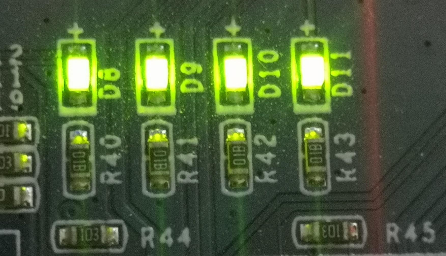
Let's take a look at the led circuits in the schematic diagram.
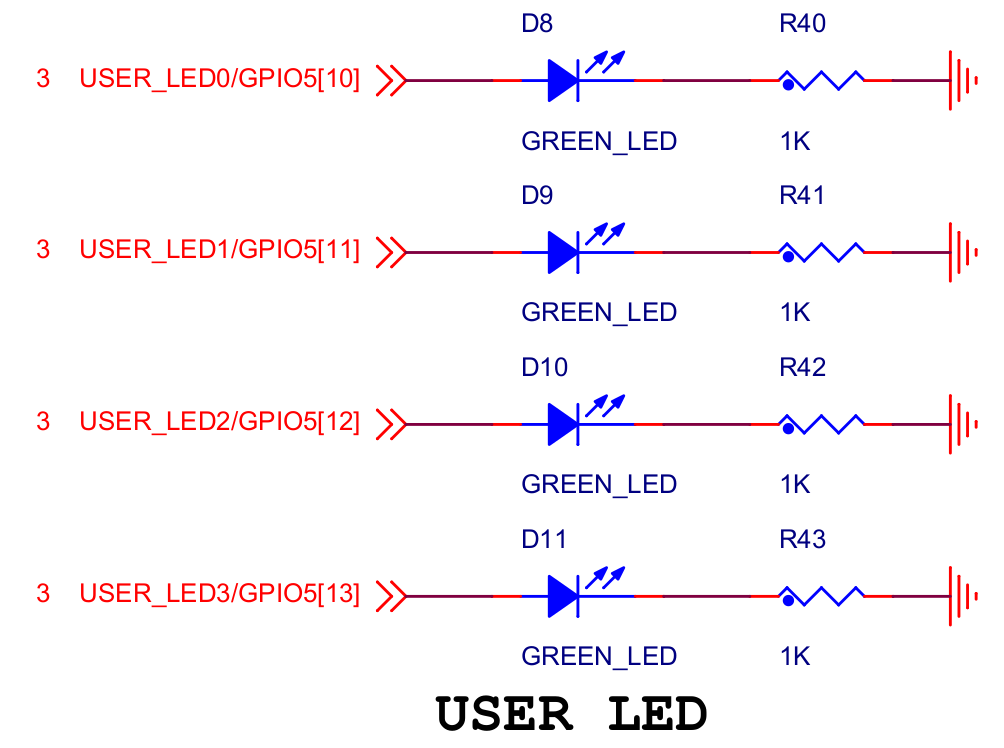
It shows that if you pull up the GPIO pin, the corresponding green led lightens, and vice versa. Therefore, we just need to setup GPIO5[10] to "pull down mode" to match our aim, aka. turning led D8 off.
Let's collect some information available in device tree source files.
// file: am4372.dtsi
gpio5: gpio@48322000 {
    compatible = "ti,am4372-gpio","ti,omap4-gpio";
    reg = <0x48322000 0x1000>;
    interrupts = <GIC_SPI 148 IRQ_TYPE_LEVEL_HIGH>;
    gpio-controller;
    #gpio-cells = <2>;
    interrupt-controller;
    #interrupt-cells = <2>;
    ti,hwmods = "gpio6";
    status = "disabled";
};
// file: am437x-gp-evm.dts
leds {
  pinctrl-names = "default", "sleep";
  pinctrl-0 = <&user_leds_default>;
  pinctrl-1 = <&user_leds_sleep>;

  compatible = "gpio-leds";

  led@0 {
    label = "tl437x:green:heartbeat";
    gpios = <&gpio5 9 GPIO_ACTIVE_HIGH>;
    linux,default-trigger = "heartbeat";
    default-state = "off";
  };

  led@1 {
    label = "tl437x:green:mmc0";
    gpios = <&gpio5 8 GPIO_ACTIVE_HIGH>;
    linux,default-trigger = "mmc0";
    default-state = "off";
  };

  led@2 {
    label = "user-led0";
    gpios = <&gpio5 10 GPIO_ACTIVE_HIGH>;
    default-state = "on";
  };

  led@3 {
    label = "user-led1";
    gpios = <&gpio5 11 GPIO_ACTIVE_HIGH>;
    default-state = "on";
  };

  led@4 {
    label = "user-led2";
    gpios = <&gpio5 12 GPIO_ACTIVE_HIGH>;
    default-state = "on";
  };

  led@5 {
    label = "user-led3";
    gpios = <&gpio5 13 GPIO_ACTIVE_HIGH>;
    default-state = "on";
  };
};

user_leds_default: user_leds_default {
  pinctrl-single,pins = <
    0x238 (PIN_OUTPUT_PULLUP | MUX_MODE7)	/* gpio5_8.gpio5_8 */
    0x23c (PIN_OUTPUT_PULLUP | MUX_MODE7)	/* gpio5_9.gpio5_9 */
    0x240 (PIN_OUTPUT_PULLUP | MUX_MODE7)	/* gpio5_10.gpio5_10 */
    0x244 (PIN_OUTPUT_PULLUP | MUX_MODE7)	/* gpio5_11.gpio5_11 */
    0x248 (PIN_OUTPUT_PULLUP | MUX_MODE7)	/* gpio5_12.gpio5_12 */
    0x24c (PIN_OUTPUT_PULLUP | MUX_MODE7)	/* gpio5_13.gpio5_13 */
  >;
};

user_leds_sleep: user_leds_sleep {
  pinctrl-single,pins = <
    0x238 (PIN_INPUT_PULLDOWN | MUX_MODE7)	/* gpio5_8.gpio5_8 */
    0x23c (PIN_INPUT_PULLDOWN | MUX_MODE7)	/* gpio5_9.gpio5_9 */
    0x240 (PIN_INPUT_PULLDOWN | MUX_MODE7)	/* gpio5_10.gpio5_10 */
    0x244 (PIN_INPUT_PULLDOWN | MUX_MODE7)	/* gpio5_11.gpio5_11 */
    0x248 (PIN_INPUT_PULLDOWN | MUX_MODE7)	/* gpio5_12.gpio5_12 */
    0x24c (PIN_INPUT_PULLDOWN | MUX_MODE7)	/* gpio5_13.gpio5_13 */
  >;
};

&gpio5 {
    status = "okay";
    ti,no-reset-on-init;
};
The gpio5 definition in am4372.dtsi file shows the GPIO chip 6th definition (starting from 0).
Its GPIO model is compatible with ti,omap4-gpio, which documentation is found at /Documentation/devicetree/bindings/gpio/gpio-omap.txt in the Linux source tree.
Here, let me explain about some magic numbers appearing in the device tree source.
-
gpio@48322000,reg = <0x48322000 0x1000>-
The number
48322000or0x48322000is the starting memory mapped address of GPIO5. -
Start address can be found in
Table 2-3. L4_PER Peripheral Memory Mapin TRM at P148. -
0x1000is the length of address space assigned to this device. -
The length can be calculated via
End address - Start address. Also available at TRM P148.
-
The number
-
GIC_SPI 148 IRQ_TYPE_LEVEL_HIGH-
It specifies the interrupt type and can be found at /Documentation/devicetree/bindings/arm/gic.txt in the Linux source tree.
-
GIC_SPIisshared processor interruptsinterrupt type meaning that the interrupt might be processed by any of the SMP cores.- Further information available as ARM spec GIC Arch 2.0 and GIC Arch 3.0, 4.0
-
148is the interrupt number -
IRQ_TYPE_LEVEL_HIGHis the interrupt flag detailed in the documentation. CurrentlyIRQ_TYPE_LEVEL_HIGHshows that the interrupt is triggered at high level.
-
-
statuswas disabled inam4372.dtsi, then re-enabled inam437x-gp-evm.dts
Further, let's take a look at the led definitions in am437x-gp-evm.dts file.
-
compatible = "gpio-leds";-
gpio-ledshere shows that the leds are compatible withgpio-ledsdriver (/drivers/leds/leds-gpio.c).
-
-
linux,default-trigger-
Default trigger of
LED0isheartbeattrigger which driver is found at (/drivers/leds/trigger/ledtrig-heartbeat.c). -
Default trigger of
LED1ismmc0trigger which driver is implemented in the MMC driver (/drivers/mmc/).
-
Default trigger of
-
gpios = <&gpio5 10 GPIO_ACTIVE_HIGH>;-
&gpio5 10shows that the led is controlled byGPIO5_10pin. -
GPIO_ACTIVE_HIGHshows that the GPIO pin pulls up when it is active.
-
For pinctrl-single,pins part, let's take 0x240 (PIN_INPUT_PULLDOWN | MUX_MODE7) /* gpio5_10.gpio5_10 */ as an example.
-
The pin attribute is found in the processor datasheet where
gpio5_10specifically, is in Table 4-10, on Page 38.-

-
When adapting GPIO functionality, the pin should be multiplexed in
0x7mode. Its ball-reset-mode isMode7and it can takePULL-UP / PULL-DOWNIO types.
-
-
The pin address
0x240is calculated as following:-
There're 2 places to find the
GPIO5_10register address.-
In Table 7-11
CONTROL_MODULE Registers, in Section 7.3.1, on Page 647.
-
In Section 7.3.1.190, on Page 987.

-
-
Take a look at the
pinmuxdefinition found atam4372.dtsi.-
// file: am4372.dtsi am43xx_pinmux: pinmux@44e10800 { compatible = "ti,am437-padconf", "pinctrl-single"; reg = <0x44e10800 0x31c>; #address-cells = <1>; #size-cells = <0>; #interrupt-cells = <1>; interrupt-controller; pinctrl-single,register-width = <32>; pinctrl-single,function-mask = <0xffffffff>; }; -
reg = <0x44e10800 0x31c>;tells us that all pin control registers starts from0x800.
-
-
Finally, the
GPIO5_10register address is calculated as0x240 (0xA40 - 0x800).
-
At last, we can now handle the turning off led D8 aim, and yet there're two ways to get it done.
The easy way is simple. In led@2 definition, just simply turn the default-state to off
led@2 {
	label = "user-led0";
	gpios = <&gpio5 10 GPIO_ACTIVE_HIGH>;
	default-state = "off";
};
The harder way involves 3 steps:
-
Step 1: comment out the
led@2's definition./* * In `leds` comment out `led@2`'s definition, as following */ // led@2 { // label = "user-led0"; // gpios = <&gpio5 10 GPIO_ACTIVE_HIGH>; // default-state = "on"; // }; -
Step 2: comment out the
gpio5_10's default settings./* * In `user_leds_default` and `user_leds_sleep`. Comment out `gpio5_10` default settings. */ user_leds_default: user_leds_default { pinctrl-single,pins = < 0x238 (PIN_OUTPUT_PULLUP | MUX_MODE7) /* gpio5_8.gpio5_8 */ 0x23c (PIN_OUTPUT_PULLUP | MUX_MODE7) /* gpio5_9.gpio5_9 */ /* 0x240 (PIN_OUTPUT_PULLUP | MUX_MODE7)*/ /* gpio5_10.gpio5_10 */ 0x244 (PIN_OUTPUT_PULLUP | MUX_MODE7) /* gpio5_11.gpio5_11 */ 0x248 (PIN_OUTPUT_PULLUP | MUX_MODE7) /* gpio5_12.gpio5_12 */ 0x24c (PIN_OUTPUT_PULLUP | MUX_MODE7) /* gpio5_13.gpio5_13 */ >; }; user_leds_sleep: user_leds_sleep { pinctrl-single,pins = < 0x238 (PIN_INPUT_PULLDOWN | MUX_MODE7) /* gpio5_8.gpio5_8 */ 0x23c (PIN_INPUT_PULLDOWN | MUX_MODE7) /* gpio5_9.gpio5_9 */ /* 0x240 (PIN_INPUT_PULLDOWN | MUX_MODE7)*/ /* gpio5_10.gpio5_10 */ 0x244 (PIN_INPUT_PULLDOWN | MUX_MODE7) /* gpio5_11.gpio5_11 */ 0x248 (PIN_INPUT_PULLDOWN | MUX_MODE7) /* gpio5_12.gpio5_12 */ 0x24c (PIN_INPUT_PULLDOWN | MUX_MODE7) /* gpio5_13.gpio5_13 */ >; }; -
Step 3: manually setup
gpio5_10.// Manually setup led@2, GPIO5[10] to not lightened. (After `leds` definition) led@2 { pinctrl-single,pins = < 0x240 (PIN_INPUT_PULLDOWN | MUX_MODE7) /* gpio5_10.gpio5_10 */ >; };
Reference: In a device tree for AM335x, how do I know what pinctrl values to use?
 Comments (0)